Circuit Simulation Lab / PCB Design Lab. / PSPICE Lab / CAD Lab
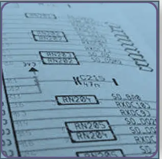
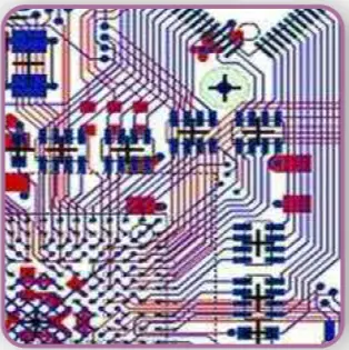
Target 3001 is a CAD/CAE – S/w for Integrated PCB Design Suite consists of :
- Schematic,
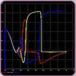
- A/D Mixed Mode Simulation,
- Contour Autorouter
- Autoplacer,
- PCB Layout,
- 3D view,
- EMC Analysis check,
- Frontpanel Layout.

It provides Manufacturing Data for production processes of all industry standards.
Why should you use it?
- 32-Bit Power with Windows NT/2000/ME/XP/Vista Windows graphical user interface
- Toggle between schematic and layout or have both in separate windows besides each other. Several
projects can be opened simultaneously - Renaming, renumbering, pin- or gate swaps are automatically implemented to schematic and layout
- Highest accuracy: vector graphics with a resolution of 1nm = 1/1.000.000 mm (units metrical or imperial)

- 1 cm PCB is 1 cm on screen (true coordinates) when scale is set 100% Any grid, rotate at any angle
- Over 36.000 components.
- Components can be edited after insertion to schematic or layout 50 steps undo/redo
- Clipboard inserts your vector drawings also into MS-Word, OpenOffice or similar lossless for means of
documentation*Comfortable Library Browser for search, download, edition of components - Interactive automatic placement of components (Autoplacer), placment of components according tofigures (cluster placement, alignment assistant)
- Two internal autorouters allowing different strategies of autorouting
- Interface to external autorouter “ELECTRA”,
- Import of Protel* and Eagle* projects, direct export to Eagle
- Import of netlists in OrCAD*-Multiwire and Mentor* format, TARGET-ASCII und Gerber*-Format
- Creation of netlists in Protel*, OrCAD*, Calay* and Pads FORMAT
- Creation of BoMs in Protel*, OrCAD* and Calay* format
- Read in of Bitmaps (Logo etc.) Export to all Windows printers
- Your individual project documentations multilingual (three languages possible)
- Electrical rule check (ERC) Design rule check (DRC)
- Generating all common data formats for production on button-click: Export to Gerber RS274-D*, Gerber RS274-X*, Excellon*, Sieb&Meyer*, DXF, Postscript*
- Several milling formats besides HPGL supported , Separate printing of all layers in use
- Easy creation of individual components (package and symbol, simulation model and 3D- model) having
endless component properties - Up to 256 variants of assembly within one project.
- Component Management System (CMS) with deep-links to the shops of several distributors, providing data
sheets accordingly - Network compatible, project-locking, password for libraries
- Free Updates within the current main version , Transparency of your workflow in Target 3001
- Freedom of action and flexibility maximized, interdictions and prohibitions minimized
- Straightforward logic and design in all modules
- Numerous Commercial features within the component management system (CMS)
- Protel, Eagle, OrCAD, Gerber, Excellon, Calay and PostScript are registered trademarks. All rights reserved to
the owners
GENERAL FEATURES
- 32-Bit-Windows-Power o Program And Manual Completely In
English And German Language - Toggle Between Schematic And PCB o Realtime Data
IntegrationRealtime
- Ground Plane Computation o Realtime Air Wire
Optimization o Autoplacer (Forward-/Back-Annotation) - Contour Autorouter (Shape Based, Gridless) o Hybrid
Autorouter oInterface To The Autorouter Electra (Specctra
® Compatible) Drag & Drop Library Browser o Drag & Drop
Component Placement - Clipboard As A Documentation Interface o Intuitive
Windows User Interface o Free Version “Discover” Can Be
Used As Viewer o Undo/Redo (50 Steps) - Interfaces:
o Gerber in/Out o Xgerber o Excellon
o Sieb & Meyer o Dxf o Postscript
o Bitmap In o Ascii In/Out (Open Data-Interface)
o Xml In/Out o Generic Hpgl Out
o Smart Gerber (Combines Both) - Insulation Milling As Outline Engraving (Directly From The
Program!) - Maximum Accuracy: Vector Graphics, Resolution: 1nm =
1/1.000.000mm = 1/25.400.000 Inch - World Coordinates: 1 Inch On Screen = 1 Inch On PCB (When
Zoom = 100%) - 1.2m X 1.2m PCB-/Schematic Area, Up To 100 PCB Layers, Up To
100 Schematic Pages - Components In Current Project Directly Editable: Change Pad,
Modify Package Etc. - Flip-Chips And Ball-Grid-Arrays (Bgas) Supported
- Rotation By Any Angle E.G. Chip On Board Technology
- Free Displacable Tools
- Hierarchical Design By Block Diagrams
- Generation Of Alternative Assemblies In Schematic And Layout
(Variants) - Project Browser In Tree View Technique
- Symbol Assistant & Package Assistant
- Outline Assistant For Easy Generation Of Outlines With Breakouts
- Outlines Of Any Shape
- Color Code Calculator For Resistors And Capacitors
- Calculation Of The Track Width For High Current

- Online Help System & Frontpanel Engraving Tool
- Texts In 3 Languages Simultaneously
- Update Manager For Automatic Program And Driver Updates
- Automatic Library Updates
- Alignment Assistant (Allows Geometrical Alignment Of A
Certain Number Of Identic Components) - In Schematic Mode
- Permanent Forward-Annotation To PCB
- More Than 36,000 Logic Components (Din/Ieee) On The
Component Server ( Internet Access Needed) - Common Components Provided For Local Storage
- Automatic Component Numbering
- Inserted Symbols Still Can Be Edited Or Adapted
- Library Browser For Easy Library Management
- Component Management System (Cms)
