SEMCAD X SOLUTIONS

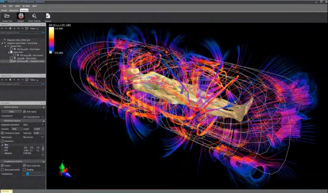
SEMCAD X is the latest generation of 3-D FDTD & FIT full-wave simulation software offering unprecedented levels of user-friendliness, speed & memory efficiency. Its application range has been greatly extended by, e.g., effective GA optimization of parametrized CAD derived structures and superior speed (>50x faster than others). Unique enhancements to the GUI, including the ACIS® CAD modeler and the ultra-fast OGL renderer allow the analysis and design of real-world configurations without any compromise.

  • ANTENNA SOLUTION : for transceivers, remote sensing, human interaction, etc.

  • MED SOLUTION : for implants, MRI systems, coil design, compliance, EM-thermal analysis, etc.

  • OPTICS SOLUTION : for non-/linear photonic crystals, switches, modulators, etc.

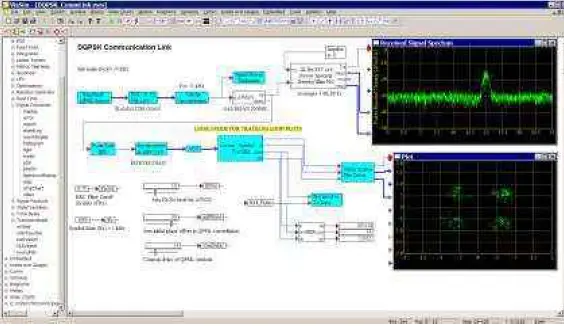
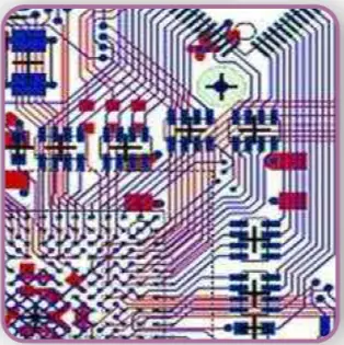
  • EMC SOLUTION : for signal integrity, interference, ESD, etc.

  • QS SOLUTION : for static, low & intermittent frequencies, motors, transformers, human interaction, etc.

Applications areas : Advanced Applications, Mobile Phone Simulations, MedTech Optimization, Antenna Design, Low Frequency, circuit/EM Cosimulatios, ECM&EMI Dosimetry, Thermal, Optics, Waveguiding Structurers, Couplers & Filters,RCS, Microstrip Circuits

Development Kits & Boards

For digital signal processing (DSP) labs, common software tools include Matlab with Simulink code composer Studio and labview, often used in conjunction with hardware like DSP development kits and trainer kits. 

Here’s a more detailed breakdown:

Software Tools:


    • MATLAB: A powerful software package for technical computing, used for simulating, experimenting with, and analyzing digital signals and systems. 

    • Simulink: A graphical environment within MATLAB, used for modeling and simulating dynamic systems, including DSP algorithms. 

    • Code Composer Studio: An integrated development environment (IDE) for embedded C/C++ code development, often used for DSP applications. 

    • LabVIEW: A graphical programming language and development environment, used for creating virtual instruments and data acquisition systems, which can be used in DSP applications. 

    • DSP Laboratory (Java): A free, educational DSP program for Windows and Linux. 

    • Keil MDK Embedded Development Tool: A tool for developing and debugging embedded systems, including DSP applications. 

Microprocessor Lab:

8085 SIMULATOR IDE is powerful application that supplies 8085 educators and developers with user friendly graphical developer environment for windows with integrate simulator (emulator), Basic compiler, assembler, disassembler and debugger for Intel 8085 8-bit microprocessor.Software available in Site License for Academic Institutes / University and grants right to the institution to use the program on all computers located on one institution site (the most suitable choice for computer labs).

8085 Simulator IDE main features:

Simulation interface showing internal processor architecture with interrupts interface,
 Memory editor for external 64K memory,
 I/O ports editor and peripheral devices interface for simulation of I/O instructions,
 Variable simulation rate, simulation statistics and simulation logging with log viewer,
 Breakpoints manager for code debugging with breakpoints support,
 8085 assembler, interactive assembler editor for beginners, 8085 disassembler,
 8085 Basic compiler with smart Basic source editor,
Support for external simulation modules,
 Extensive program options, color themes, …

8086 Microprocessor Emulator :

The Interactive System to study Assembly Language, Computer Architecture and Reverse Engineering.

The Microprocessor Emulator with Integrated Assembler. Reference, Examples and Tutorials . Virtual Hardware Inside.


Numerical Techniques Lab:

MathCAD Software:

More than 250,000 professionals worldwide are using
Mathcad to perform, document, manage and share calculation and design
work. The unique Mathcad visual format and easy-to-use whiteboard interface
integrate live, standard mathematical notation,
text and graphs into a single worksheet–making Mathcad ideal for knowledge
capture, calculation reuse, and engineering collaboration. Mathcad lets
individuals work with update-able, interactive designs, so users can capture the
critical methods and values behind each of their engineering projects.
Mathcad’s XML architecture enables organizations to go beyond powerful calculation. It delivers an openengineering
data model, enabling publishing, collaboration and integration, especially when deployed as an
organizational standard. As engineers work, Mathcad automatically creates an auditable trail of documented
calculations, thus simplifying compliance, reporting, verification and troubleshooting. These capabilities have
made Mathcad the world’s most widely used engineering calculation tool.

Communication System Design :

VisSim/Comm lets you model end-to-end communication systems at
the signal or physical level. With its full complement of communication
blocks and powerful, time-domain simulation engine, VisSim/Comm
provides fast and accurate solutions for analog, digital, and mixedmode
communication systems.
With VisSim/Comm, you can seamlessly move among the stages of
model construction, simulation, optimization, and validation. This
means that you can simulate and view signal waveforms at any phase
of the communication system chain.
VisSim/Comm add-on modules include:
VisSim/Comm C-Code: Translates Comm blocks into ANSI C code. To
translate standard VisSim blocks, you also need VisSim/C-Code.
VisSim/Comm Red Rapids: Supports real-teime data from Red Rapids
tuner cards.
VisSim/Comm Turbo Codes: Supports modeling of PCCC Turbo Codes.
VisSim/Comm Wireless LAN: Supports simulating 802.11a/b/g,
Bluetooth, and ultra wideband designs.

VHDL Lab / VLSI Lab / Digital System Design Lab

ISE Foundation Software:

ISE Foundation includes Xilinx SmartCompile technology; an industry-unique combination  of capabilities.
capabilities to solve designers’ number one design challenge – timing closure. ISE® Foundation™ Software integrates everything  you need  in a complete  logic design environment for all leading Xilinx FPGA  and CPLD products. Easy-to-use, built-in  tools and wizards make I/O  assignment, power analysis, timing-driven design  closure, and HDL simulation  quick and intuitive.ISE Foundation also includes  PlanAhead™ Lite, a subset of the  award winning PlanAhead Design and Analysis Tools to provide I/O pin planning capabilities, design analysis, floorplanning, as well as   convenient implementation control.

VLSI Design Software :

    ISE Series Ver. 10.1i or latest available version. Note: Xilinx allows an Academic Institution to have Multiple

Software Installs.

  ModelSim XE – Simulation Software for VHDL Language with Hardware Dongle for PC’s  USB Port.ModelSim XE – Simulation  Software for Verilog Language with Hardware Dongle for PC’s USB Port.DSP Application Software System Generator for DSP latest available version  Embedded System Development Software Kit latest available version. For developing embedded solutions using VLSI, including all the required development Tools
 Chip Scope-Pro for in-chip debugging with Mechatronics Make Parallel Cable & Fly Leads latest available version.

Circuit Simulation Lab / PCB Design Lab. / PSPICE Lab / CAD Lab

Target 3001 is a CAD/CAE – S/w for Integrated PCB Design Suite consists of :

  • Schematic,
  • A/D Mixed Mode Simulation,
  • Contour Autorouter
  • Autoplacer,
  • PCB Layout,
  • 3D view,
  • EMC Analysis check,
  • Frontpanel Layout.

It provides Manufacturing Data for production processes of all industry standards.

Why should you use it?

  • 32-Bit Power with Windows NT/2000/ME/XP/Vista Windows graphical user interface
  • Toggle between schematic and layout or have both in separate windows besides each other. Several
    projects can be opened simultaneously
  • Renaming, renumbering, pin- or gate swaps are automatically implemented to schematic and layout
  • Highest accuracy: vector graphics with a resolution of 1nm = 1/1.000.000 mm (units metrical or imperial)
  • 1 cm PCB is 1 cm on screen (true coordinates) when scale is set 100% Any grid, rotate at any angle
  • Over 36.000 components.
  • Components can be edited after insertion to schematic or layout 50 steps undo/redo
  • Clipboard inserts your vector drawings also into MS-Word, OpenOffice or similar lossless for means of
    documentation*Comfortable Library Browser for search, download, edition of components
  • Interactive automatic placement of components (Autoplacer), placment of components according tofigures (cluster placement, alignment assistant)
  • Two internal autorouters allowing different strategies of autorouting
  • Interface to external autorouter “ELECTRA”,
  • Import of Protel* and Eagle* projects, direct export to Eagle
  • Import of netlists in OrCAD*-Multiwire and Mentor* format, TARGET-ASCII und Gerber*-Format
  • Creation of netlists in Protel*, OrCAD*, Calay* and Pads FORMAT
  • Creation of BoMs in Protel*, OrCAD* and Calay* format
  • Read in of Bitmaps (Logo etc.) Export to all Windows printers
  • Your individual project documentations multilingual (three languages possible)
  • Electrical rule check (ERC) Design rule check (DRC)
  • Generating all common data formats for production on button-click: Export to Gerber RS274-D*, Gerber RS274-X*, Excellon*, Sieb&Meyer*, DXF, Postscript*
  • Several milling formats besides HPGL supported , Separate printing of all layers in use
  • Easy creation of individual components (package and symbol, simulation model and 3D- model) having
    endless component properties
  • Up to 256 variants of assembly within one project.
  • Component Management System (CMS) with deep-links to the shops of several distributors, providing data
    sheets accordingly
  • Network compatible, project-locking, password for libraries
  • Free Updates within the current main version , Transparency of your workflow in Target 3001
  • Freedom of action and flexibility maximized, interdictions and prohibitions minimized
  • Straightforward logic and design in all modules
  • Numerous Commercial features within the component management system (CMS)
  • Protel, Eagle, OrCAD, Gerber, Excellon, Calay and PostScript are registered trademarks. All rights reserved to
    the owners

GENERAL FEATURES 

  •  32-Bit-Windows-Power o Program And Manual Completely In
    English And German Language
  • Toggle Between Schematic And PCB o Realtime Data
    IntegrationRealtime
  • Ground Plane Computation o Realtime Air Wire
    Optimization o Autoplacer (Forward-/Back-Annotation)
  • Contour Autorouter (Shape Based, Gridless) o Hybrid
    Autorouter oInterface To The Autorouter Electra (Specctra
    ® Compatible) Drag & Drop Library Browser o Drag & Drop
    Component Placement
  • Clipboard As A Documentation Interface o Intuitive
    Windows User Interface o Free Version “Discover” Can Be
    Used As Viewer o Undo/Redo (50 Steps)
  • Interfaces:
    o Gerber in/Out                      o Xgerber                                                                o Excellon
    o Sieb & Meyer                       o Dxf o Postscript
    o Bitmap In o Ascii In/Out (Open Data-Interface)
    o Xml In/Out o Generic Hpgl Out
    o Smart Gerber (Combines Both)
  • Insulation Milling As Outline Engraving (Directly From The
    Program!)
  • Maximum Accuracy: Vector Graphics, Resolution: 1nm =
    1/1.000.000mm = 1/25.400.000 Inch
  • World Coordinates: 1 Inch On Screen = 1 Inch On PCB (When
    Zoom = 100%)
  • 1.2m X 1.2m PCB-/Schematic Area, Up To 100 PCB Layers, Up To
    100 Schematic Pages
  • Components In Current Project Directly Editable: Change Pad,
    Modify Package Etc.
  • Flip-Chips And Ball-Grid-Arrays (Bgas) Supported
  • Rotation By Any Angle E.G. Chip On Board Technology
  • Free Displacable Tools
  • Hierarchical Design By Block Diagrams
  • Generation Of Alternative Assemblies In Schematic And Layout
    (Variants)
  • Project Browser In Tree View Technique
  • Symbol Assistant & Package Assistant
  • Outline Assistant For Easy Generation Of Outlines With Breakouts
  • Outlines Of Any Shape
  • Color Code Calculator For Resistors And Capacitors
  • Calculation Of The Track Width For High Current
  • Online Help System & Frontpanel Engraving Tool
  • Texts In 3 Languages Simultaneously
  • Update Manager For Automatic Program And Driver Updates
  • Automatic Library Updates
  • Alignment Assistant (Allows Geometrical Alignment Of A
    Certain Number Of Identic Components)
  • In Schematic Mode
  • Permanent Forward-Annotation To PCB
  • More Than 36,000 Logic Components (Din/Ieee) On The
    Component Server ( Internet Access Needed)
  • Common Components Provided For Local Storage
  • Automatic Component Numbering
  • Inserted Symbols Still Can Be Edited Or Adapted
  • Library Browser For Easy Library Management
  • Component Management System (Cms)